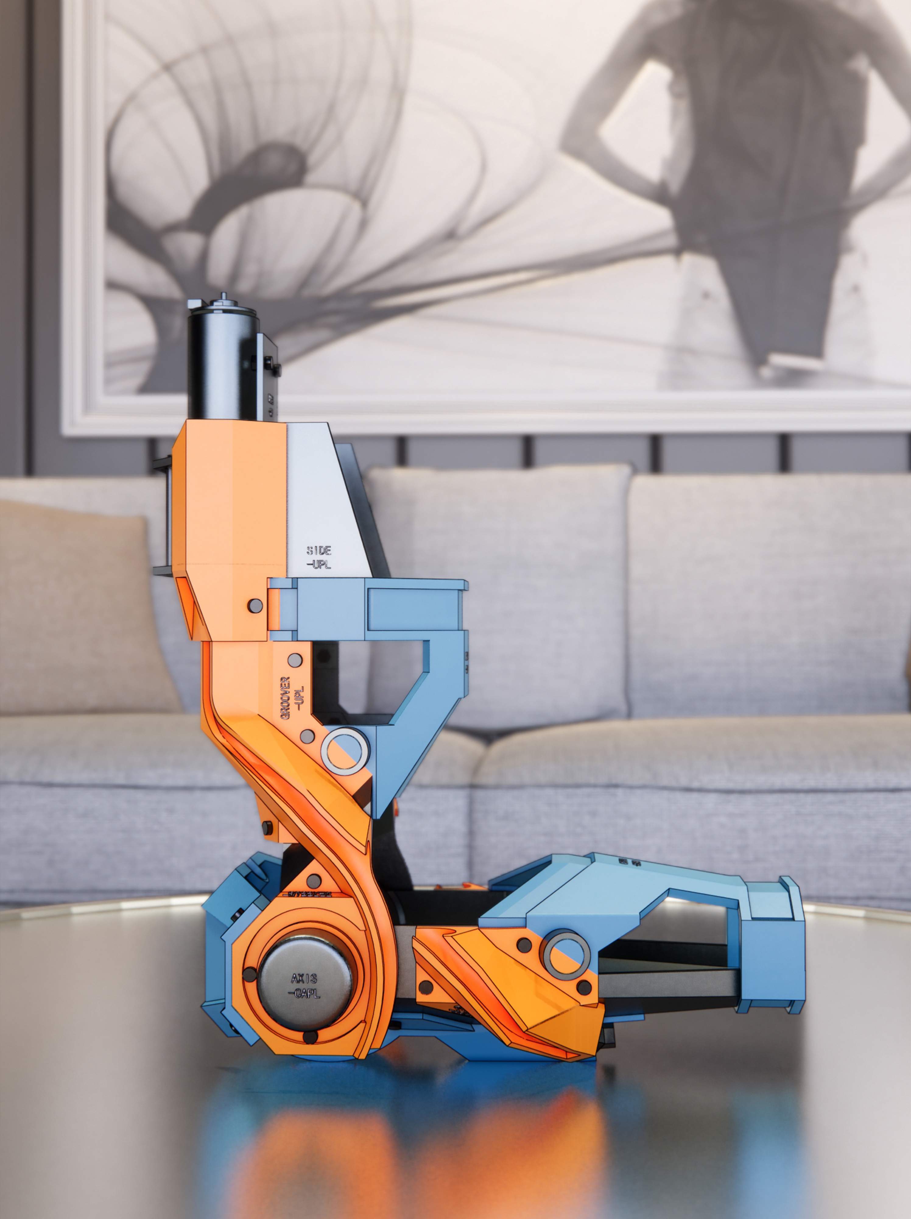
Wearable Upper Limb Exoskeleton
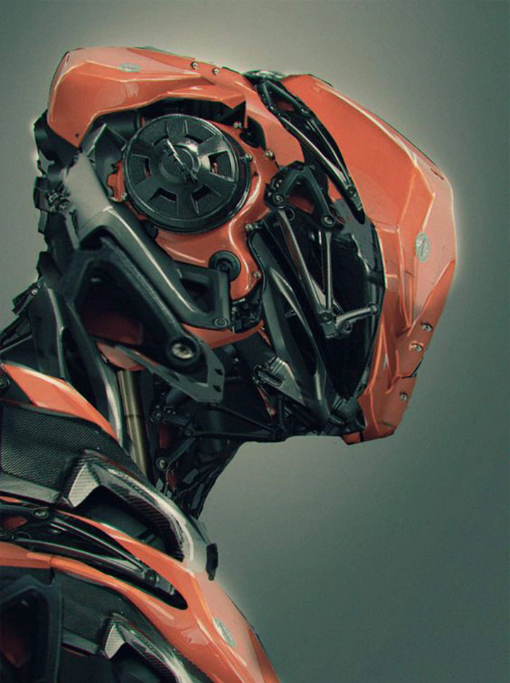
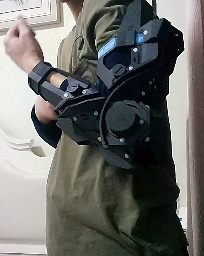
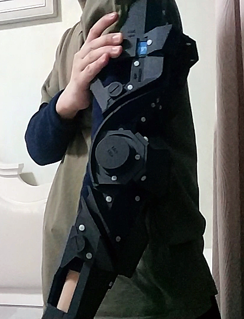
Renderings and Wearing Effect
Demo Video Test Video with Artificial Muscles
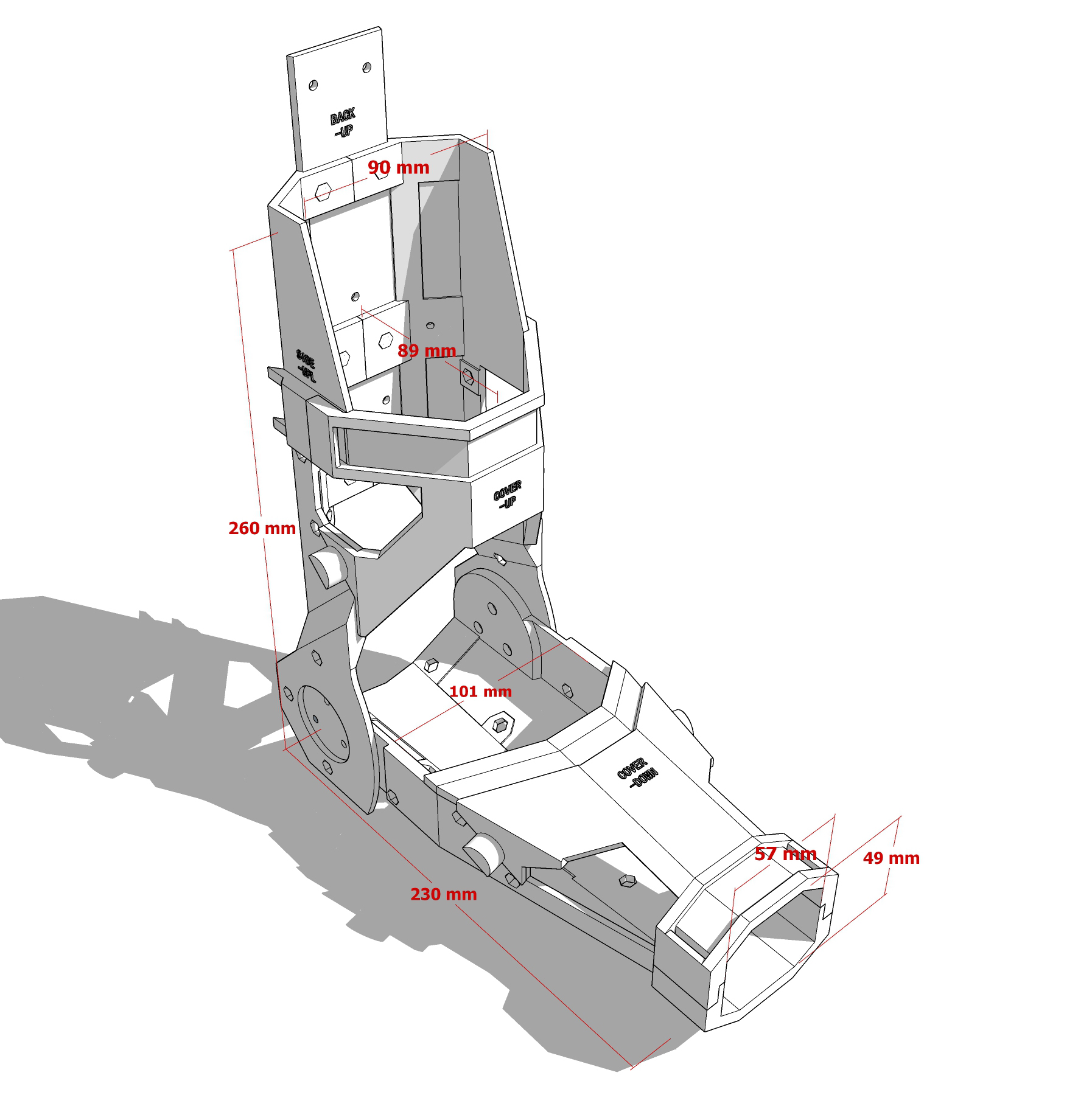
Basic Dimensions
- his exoskeleton has only one degree of freedom, providing a slightly restrictive feel when worn. The shoulder lacks a fixed component, making it prone to slipping.
- Designed specifically for my body measurements, it may not fit everyone.
- My wrist width is 60mm, thickness 40mm; the widest part of the forearm is 90mm; the distance from the wrist to the elbow pivot is 230mm; the widest part of the upper arm is 90mm. When the forearm is raised, the elbow width is 100mm, and the thickest part of the upper arm is 90mm.
Structural Description
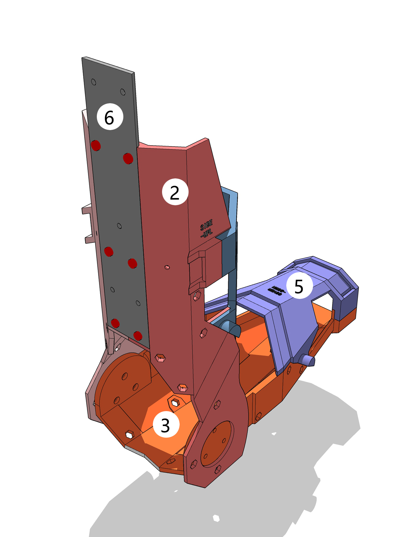
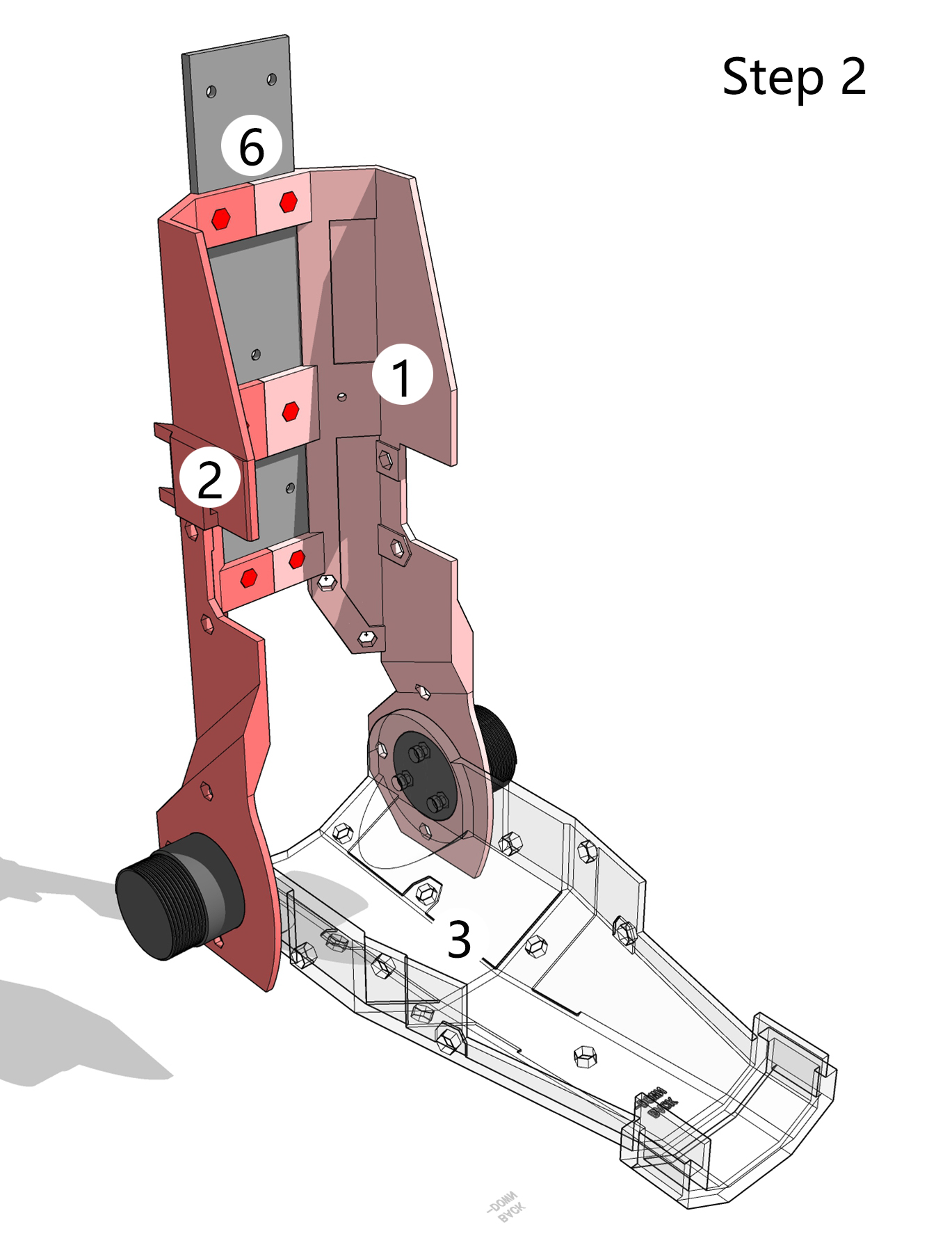
1. Exoskeleton Base Plate
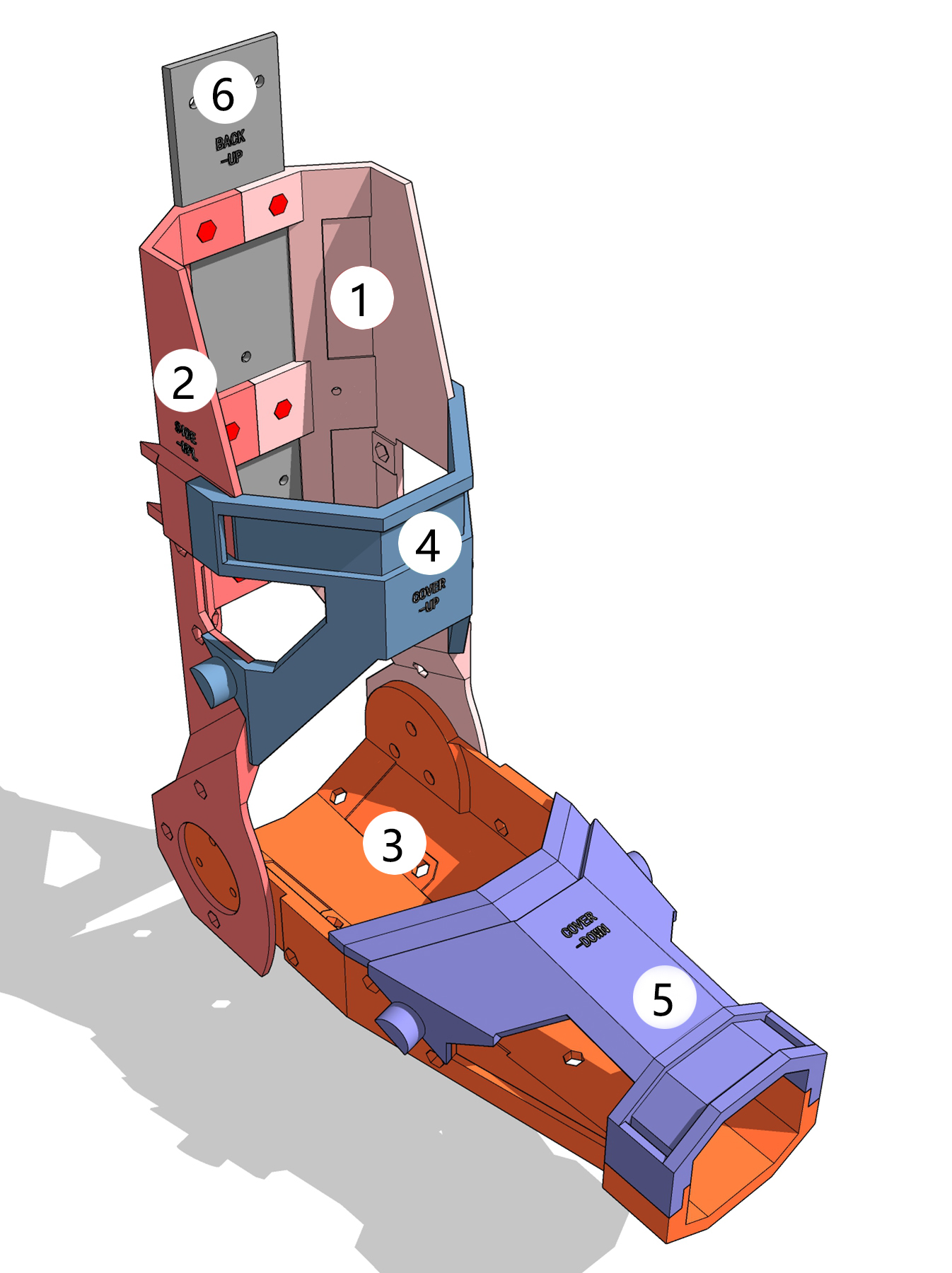
The model surface features hexagonal grooves or perforations for embedding nylon nuts (same applies below).
1 and 2 are the rear supports for the upper arm, divided into left and right parts. They are bolted together (red dots) and fixed to 6 to form a single unit.
3 is the rear support for the forearm.
4 , together with 1 and 2 , secures the human upper arm.
5 , together with 3 , secures the human forearm.
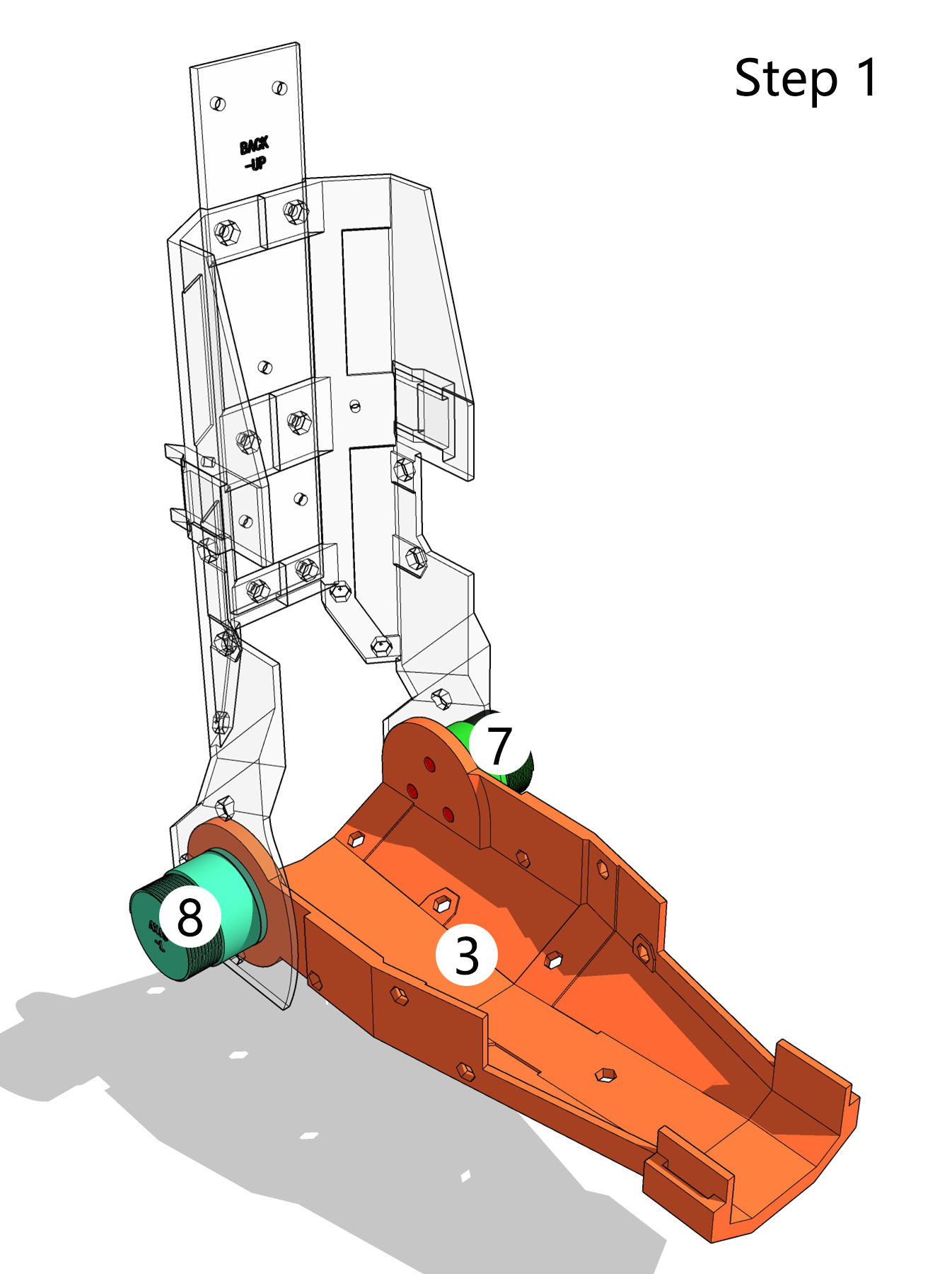
2. Elbow Rotation Axis
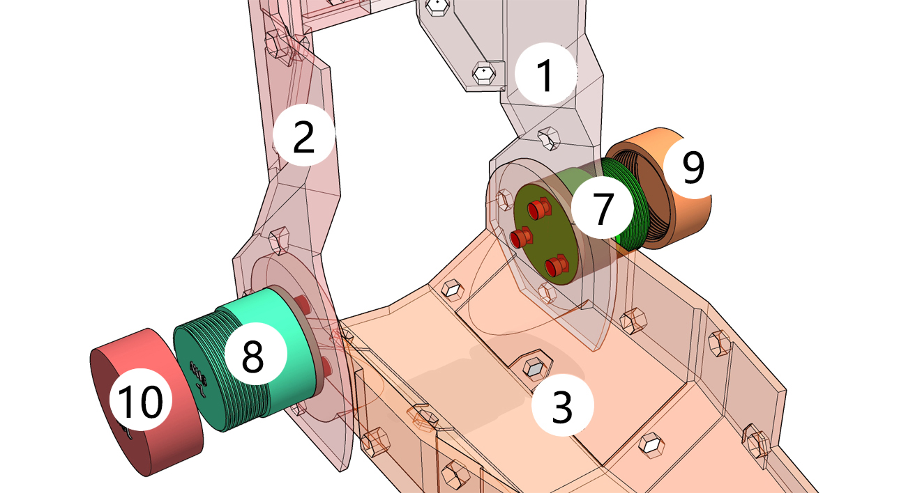
- Rotation axis 7 is fixed to 3 with bolts (red dots), and 1 can rotate around it.
- Rotation axis 8 is fixed to 3 with bolts (red dots), and 2 can rotate around it.
- 9 and 10 are nuts.
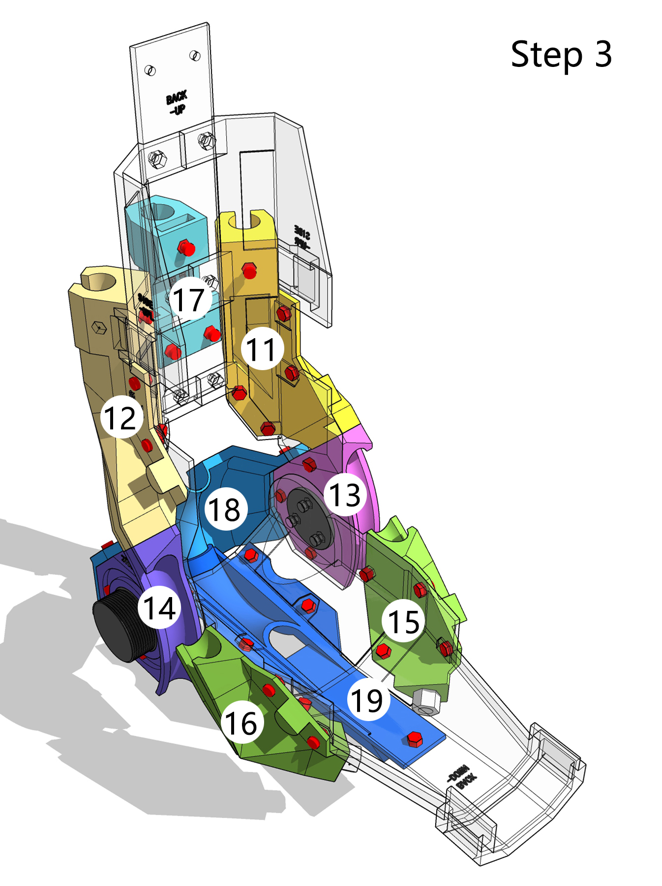
3. Artificial Muscle Grooves (for mounting soft artificial muscles)
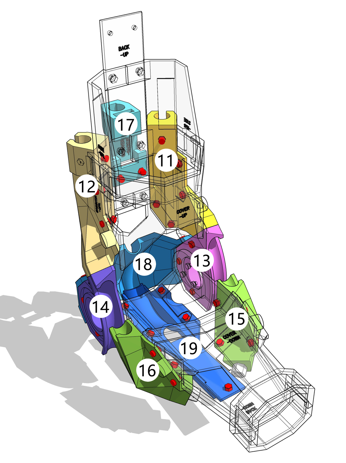
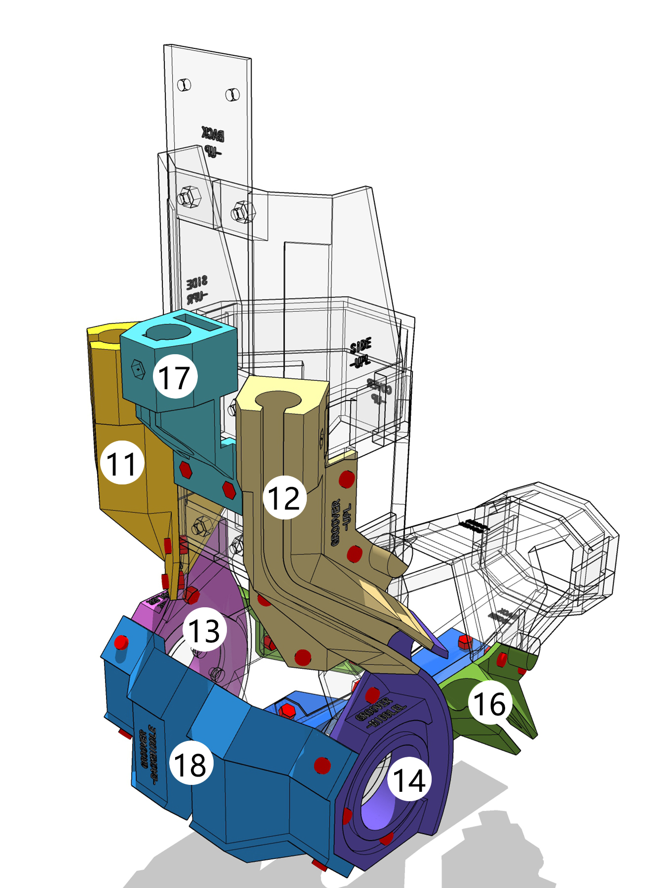
- 11 to 16 are used for mounting artificial muscles that lift the forearm. They are fixed to the base plate (transparent part) with bolts (red dots).
- 11 and 12 are artificial muscle grooves on both sides of the upper arm, with their tops connected to the power unit.
- 13 and 14 are artificial muscle grooves on both sides of the elbow, which can be mounted on the elbow rotation axes 7 and 8 for positioning.
- 15 and 16 are artificial muscle grooves on both sides of the forearm, with ends for fixing the artificial muscles.
- 17 to 19 are used for mounting artificial muscles that lower the forearm. They are fixed to the base plate (transparent part) with bolts (red dots).
- 17 is located at the center of the upper arm, with its top connected to the power unit.
- 18 is located at the elbow, fixed to 13 and 14 with bolts (red dots).
- 19 is located at the center of the forearm, with an end for fixing the artificial muscles.
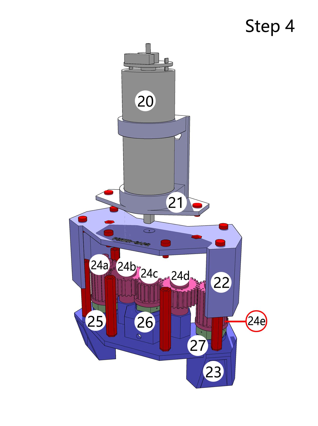
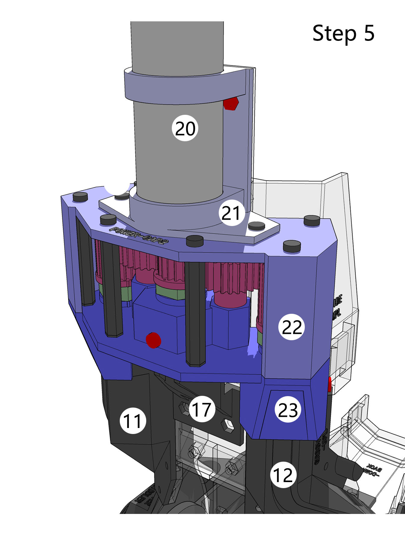
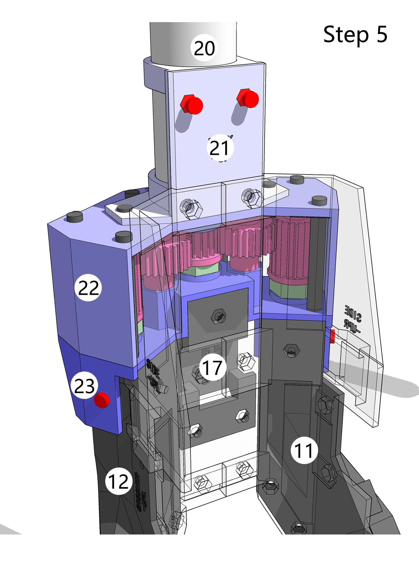
4. Power Unit
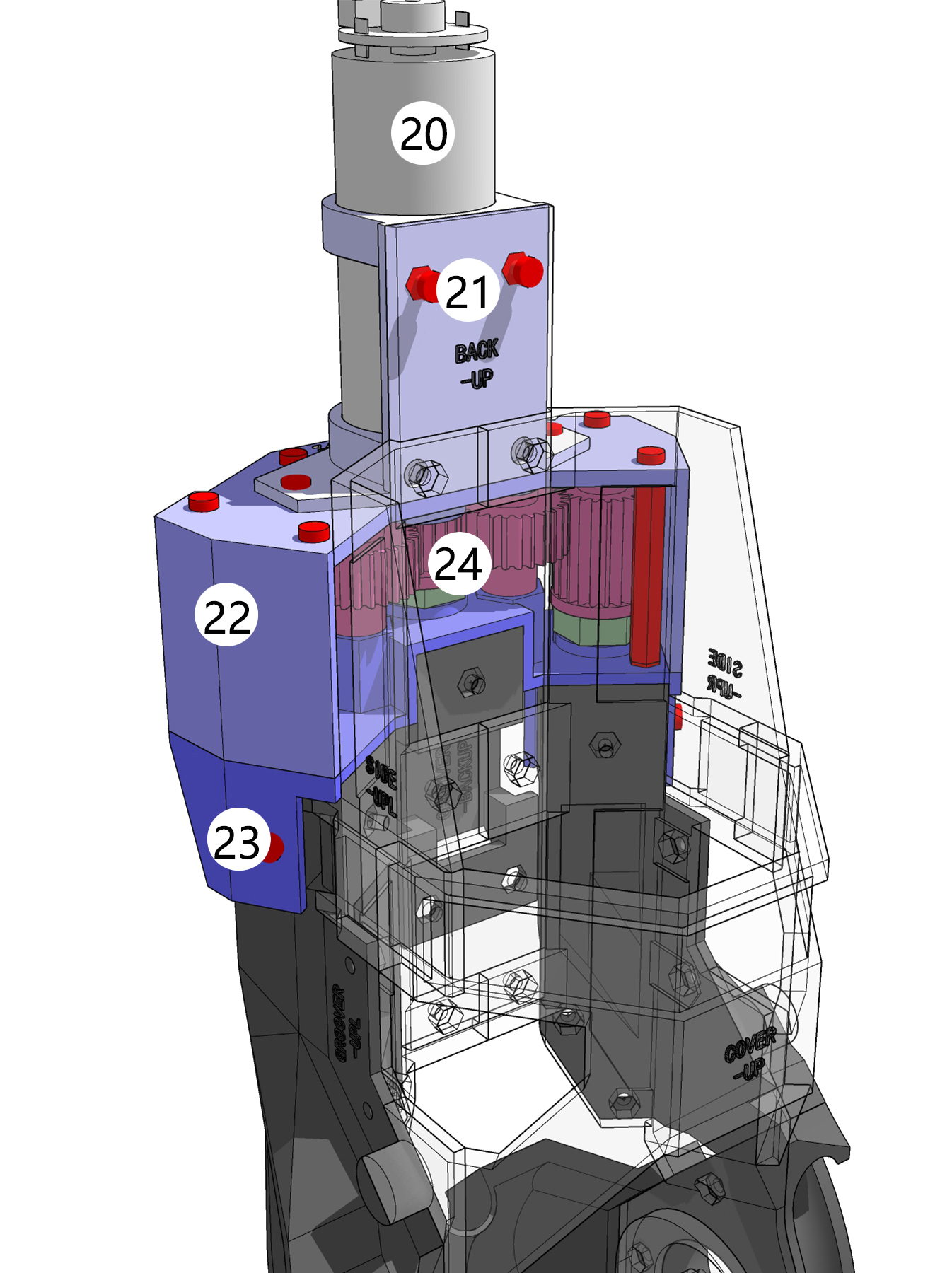
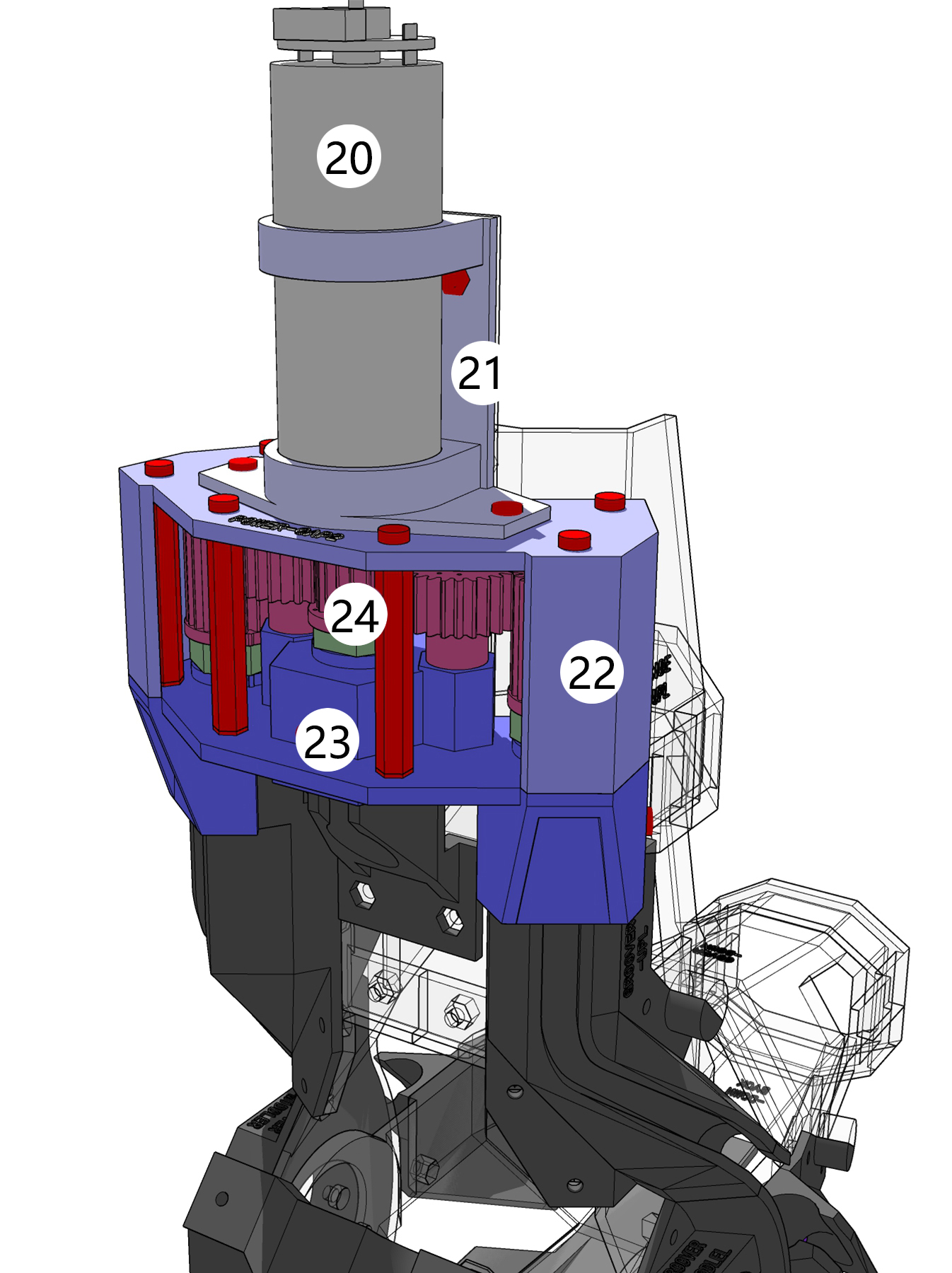
- 21 to 23 form the gearbox, housing the gear set and motor. They are assembled together with bolts (red dots).
- 21 fixes the motor 20 and is bolted (red dots) to the base plate (transparent part).
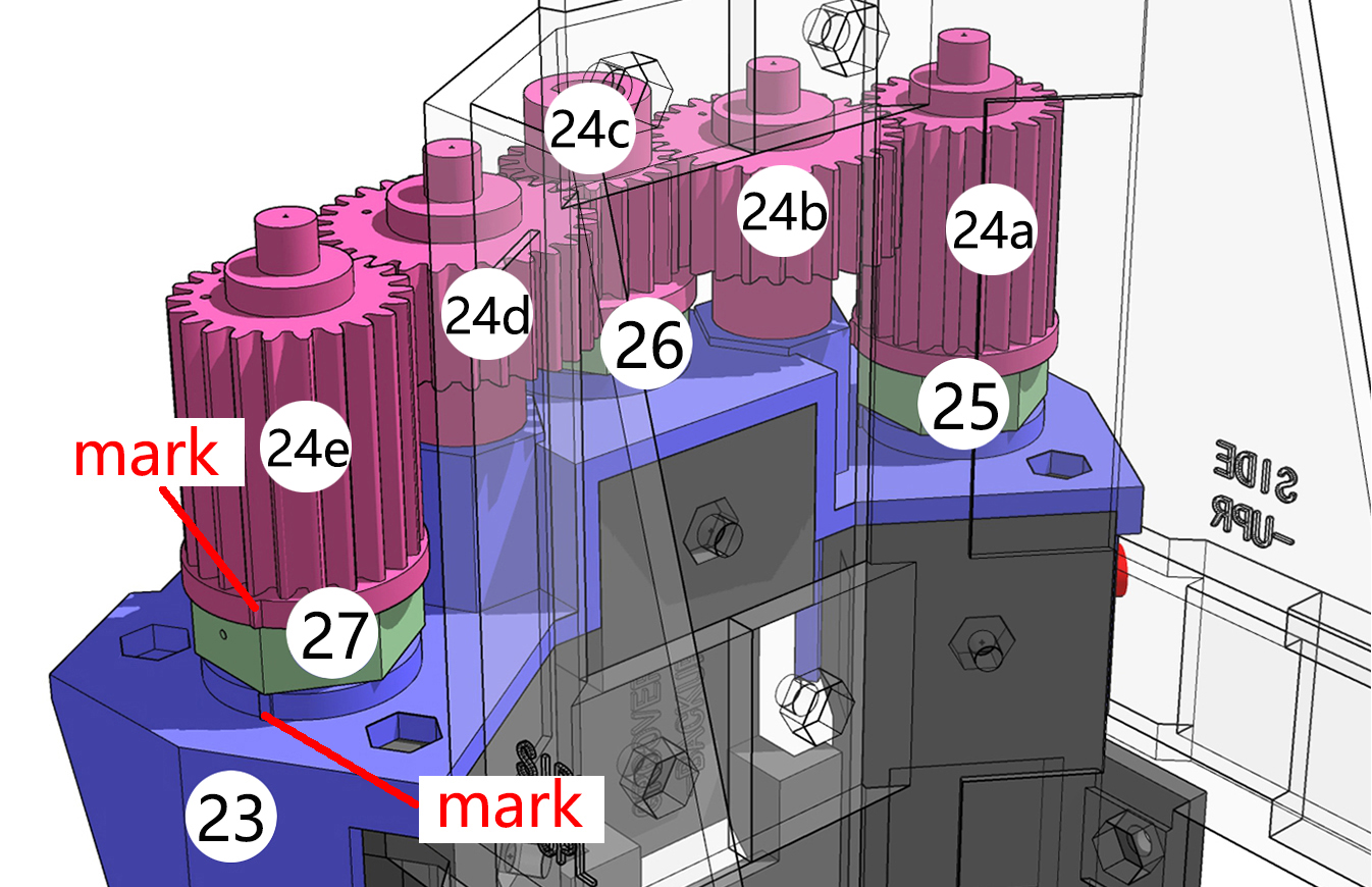
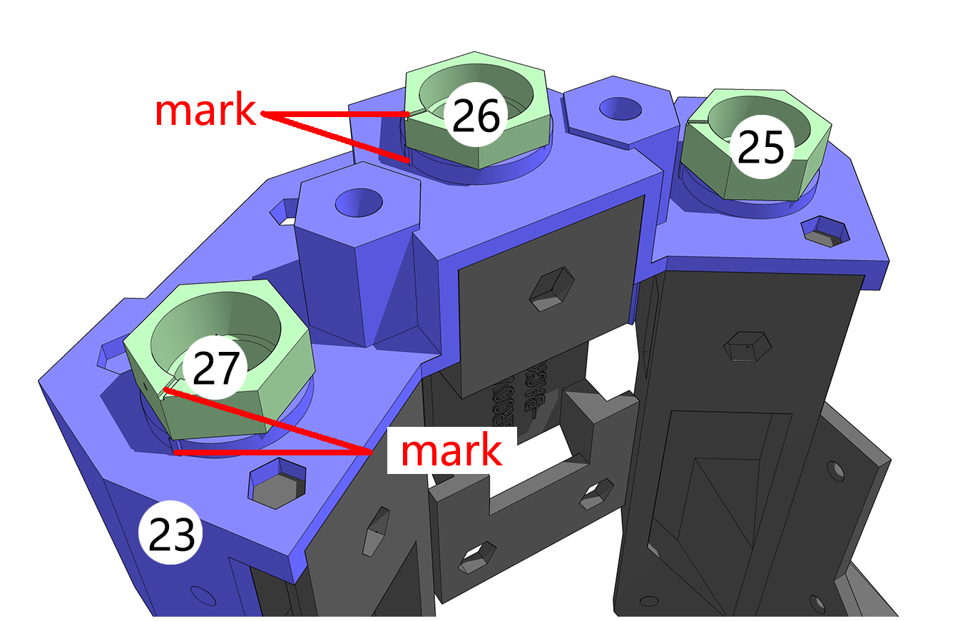
- 23 is the gearbox base plate, bolted (red dots) to the artificial muscle grooves (dark part). The three mounting platforms for the artificial muscles are marked and should align with the markings on the gear set.
- 24 is the gear set. The three gears 24a , 24c , and 24e that connect to the artificial muscles have markings at the bottom, which should align with the markings on 23 . The nylon-printed gear shafts are prone to breaking (mine broke); consider using metal shafts instead.
- 25 to 27 are used to secure the artificial muscles. They are marked and should align with the markings on 23 .
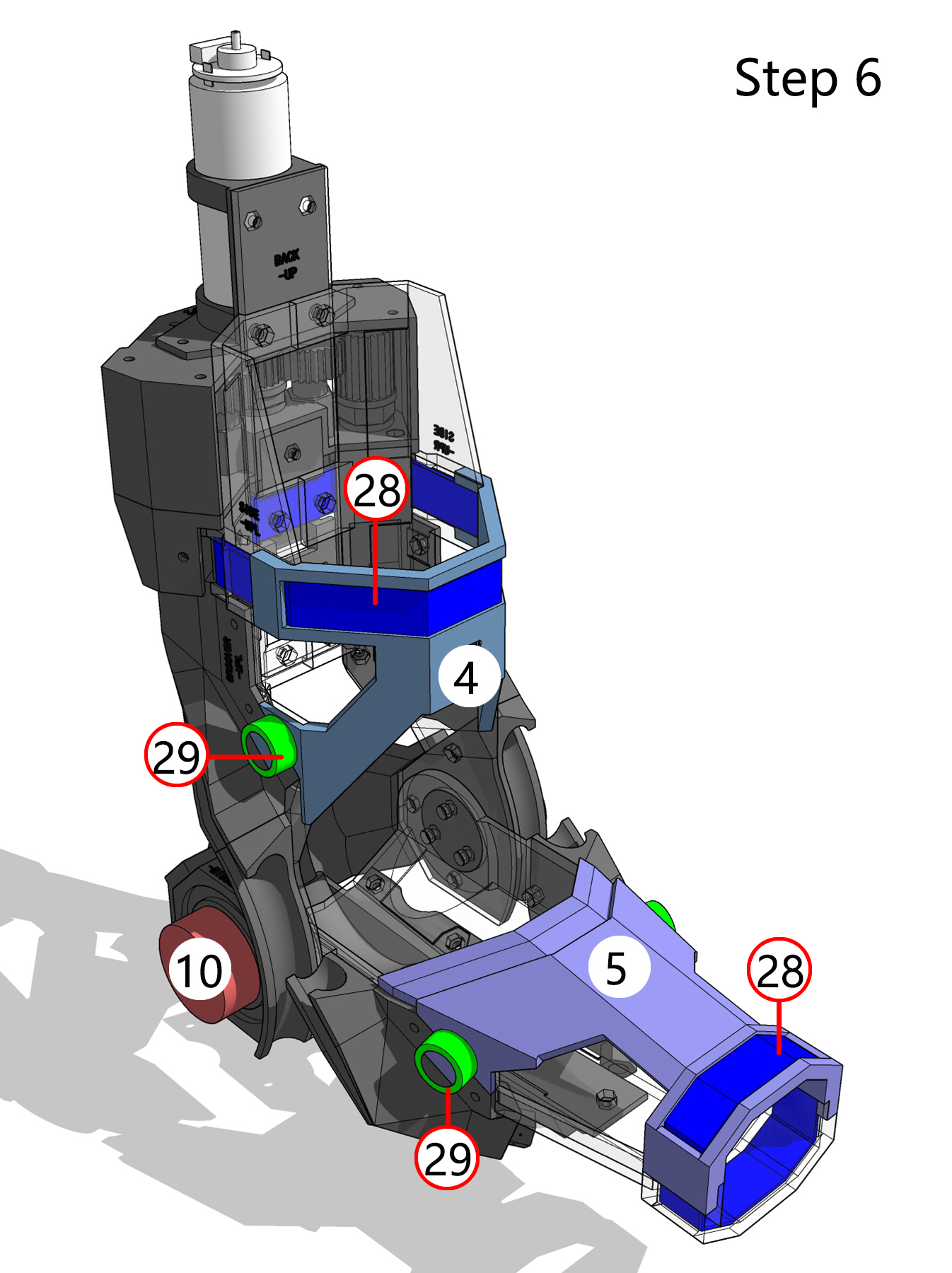
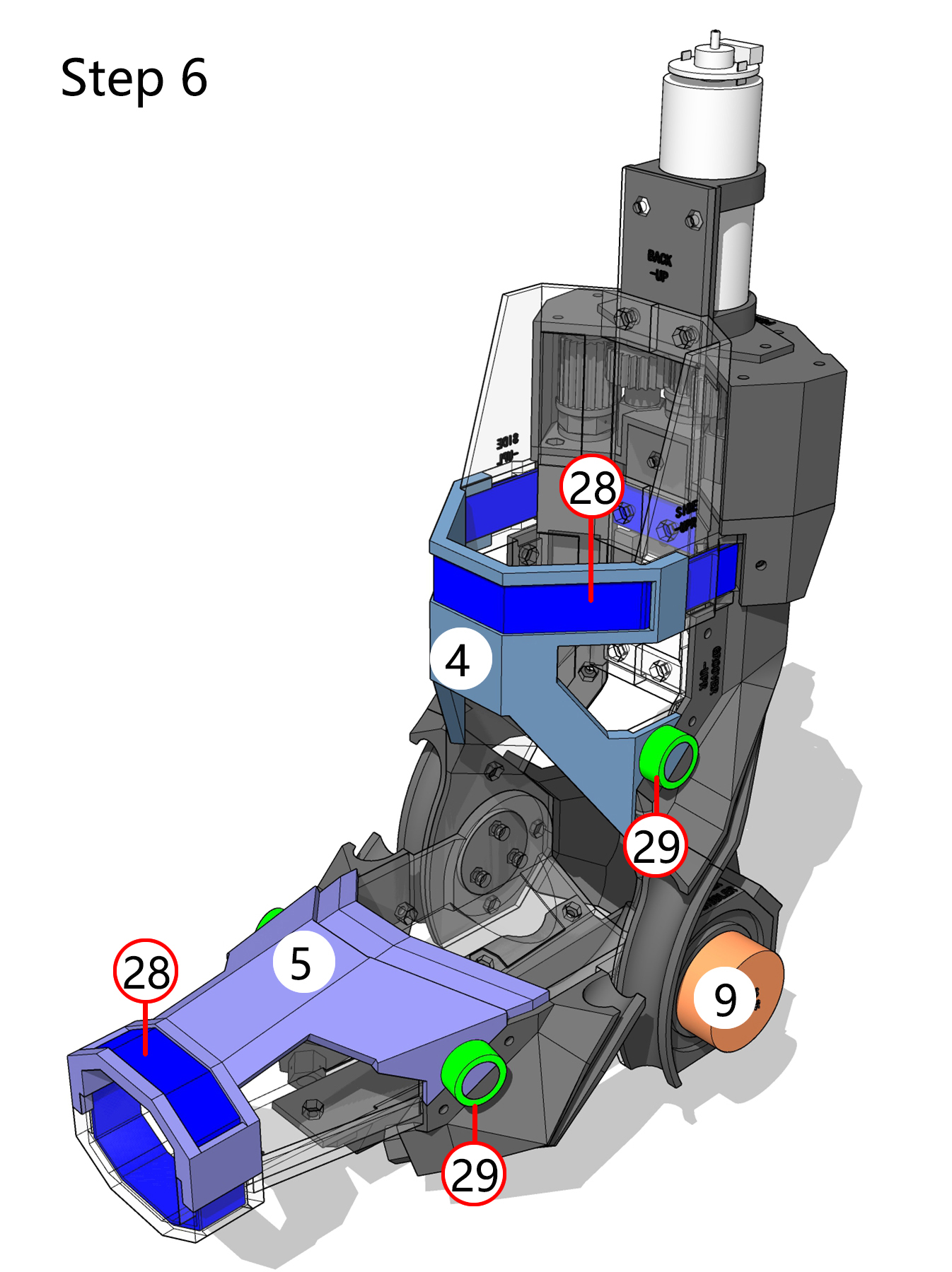
5. Restraint System
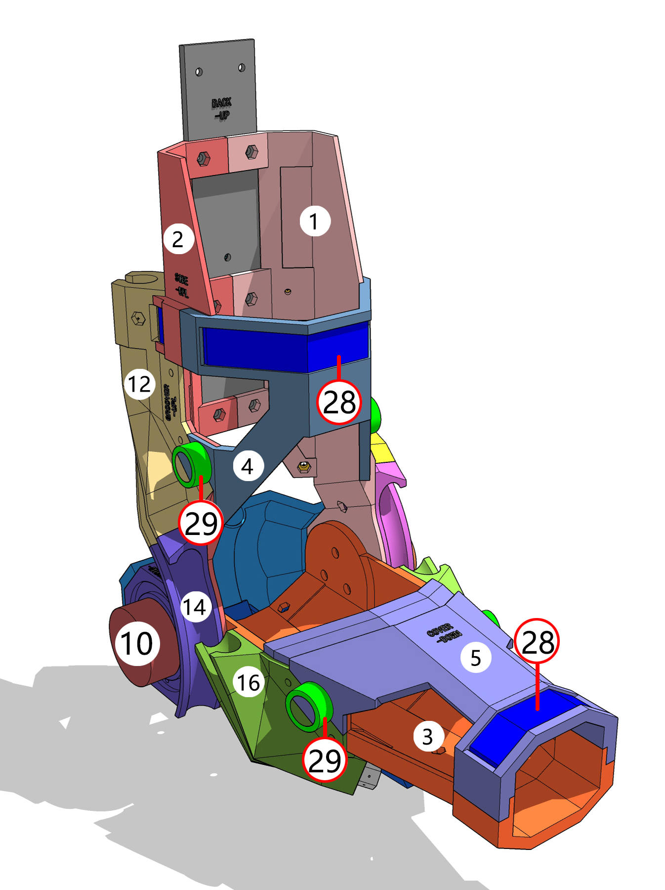
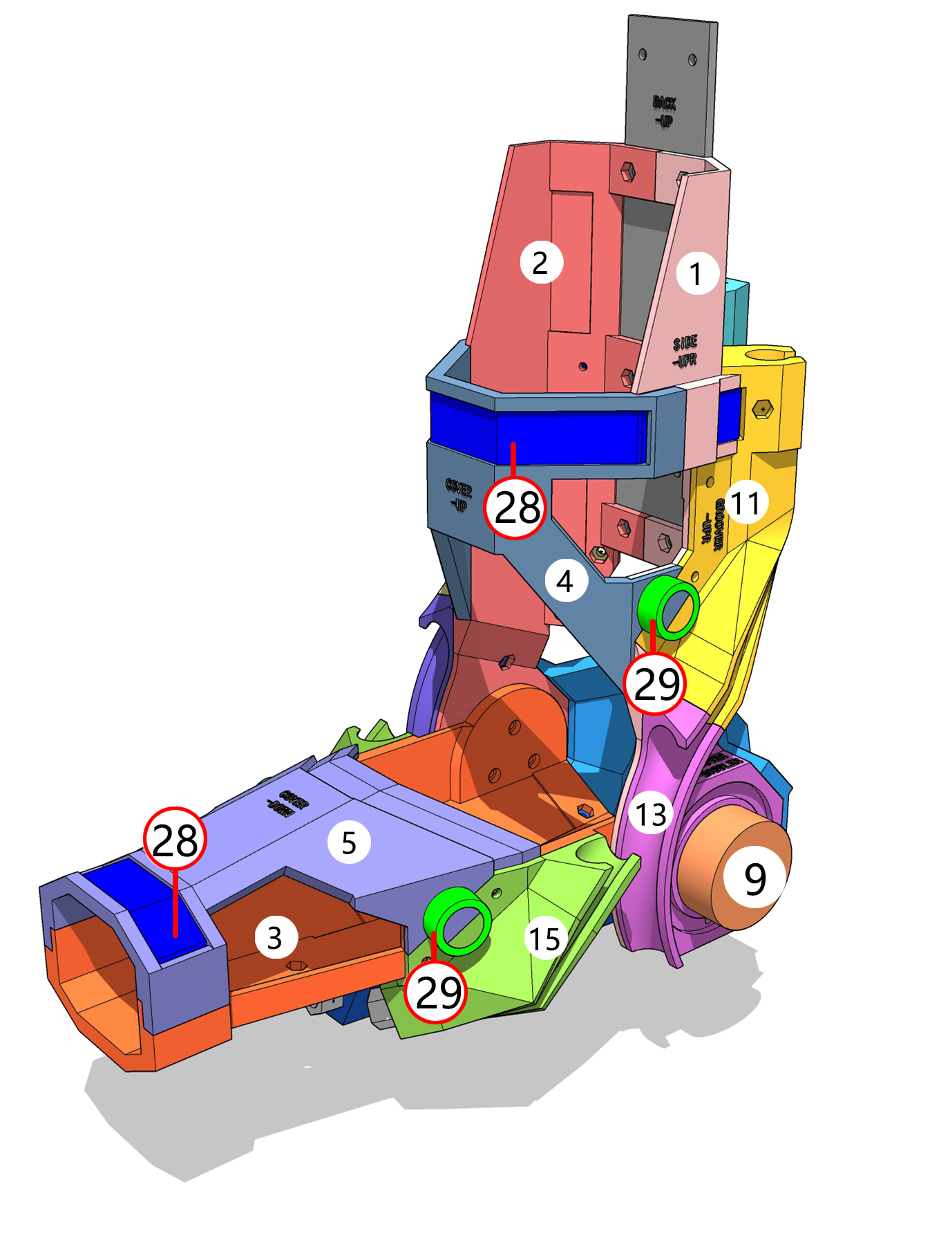
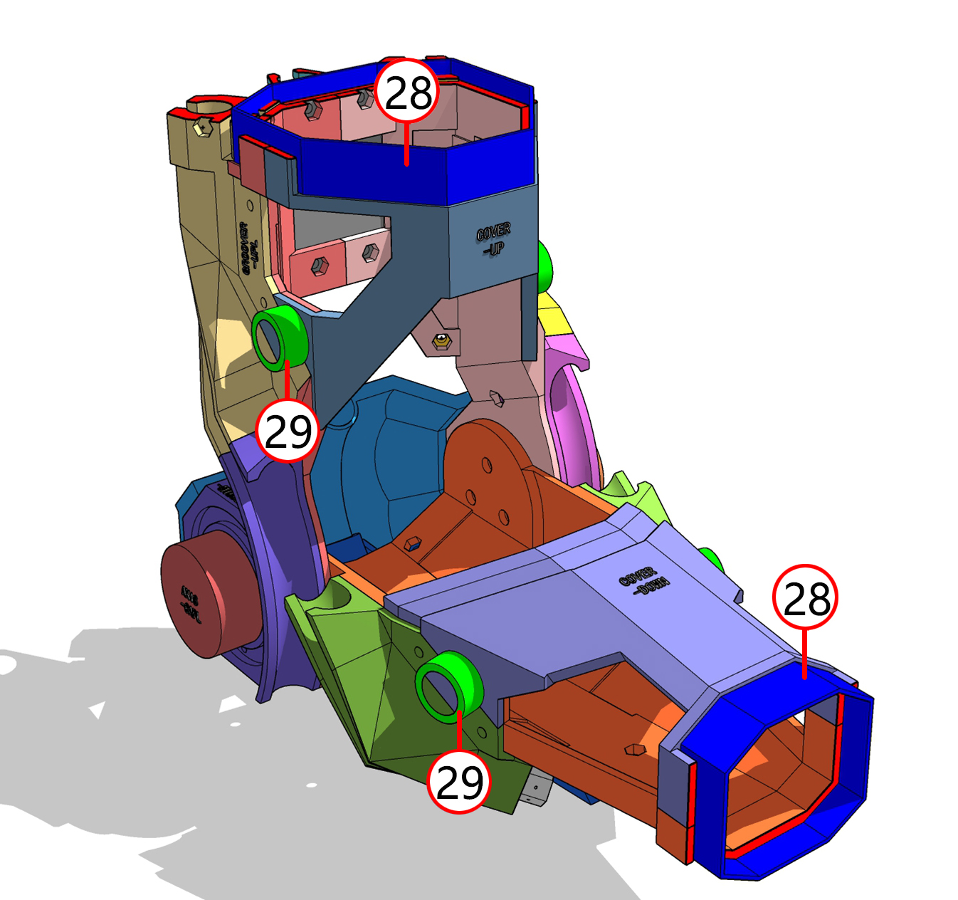
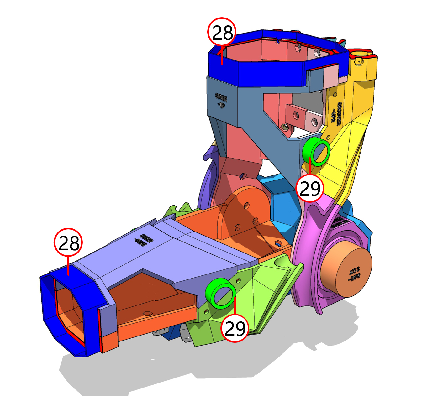
- 28 Velcro straps, 29 circular buckles. The circular buckles used here are unsuitable and easily detach; nuts might be a better alternative.
- 9 and 10 are nuts used to further secure the elbow muscle grooves 13 and 14 .
6. Artificial Muscle Path Planning
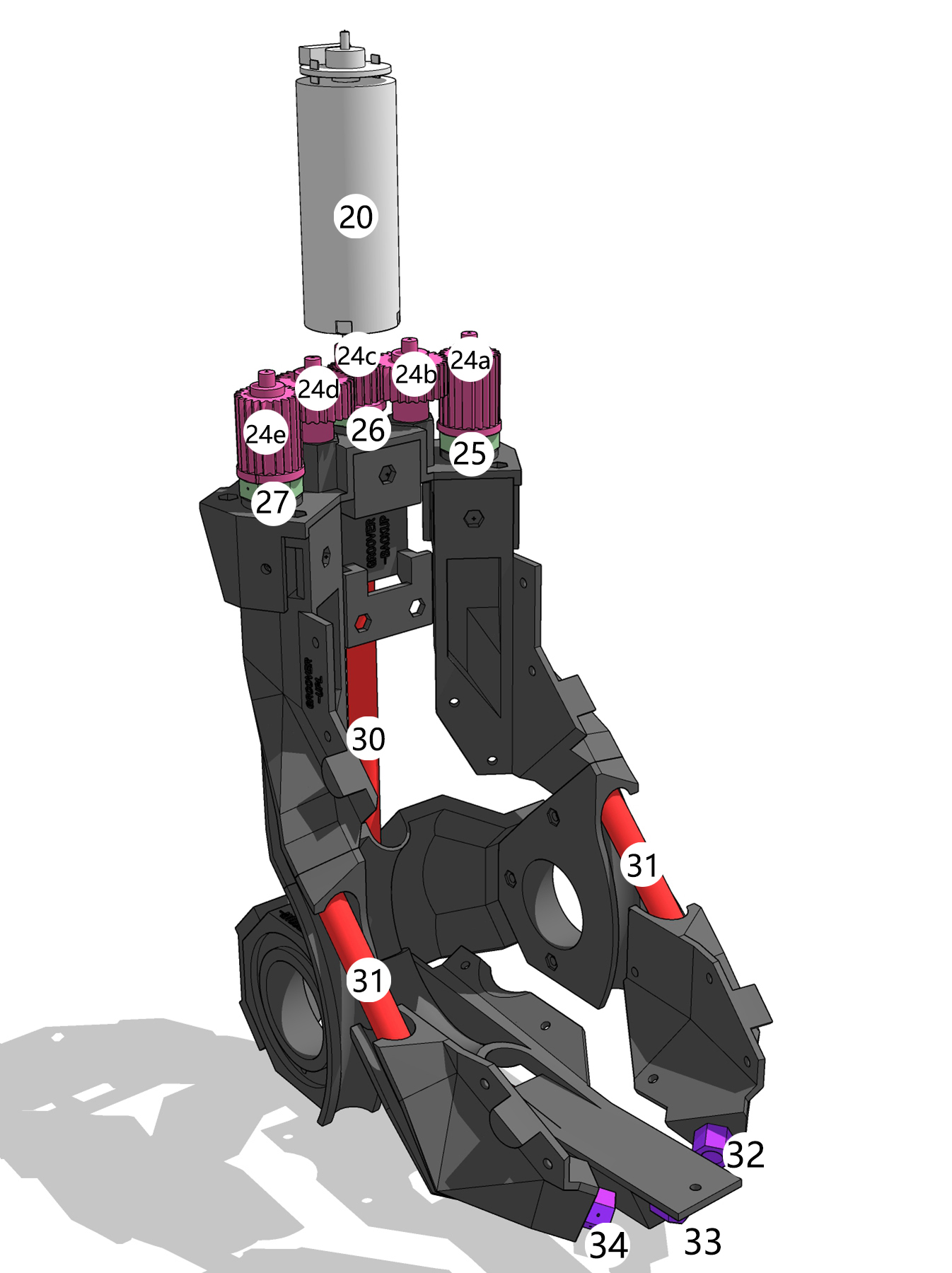
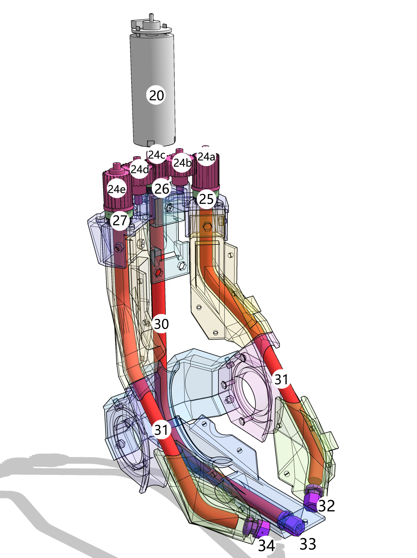
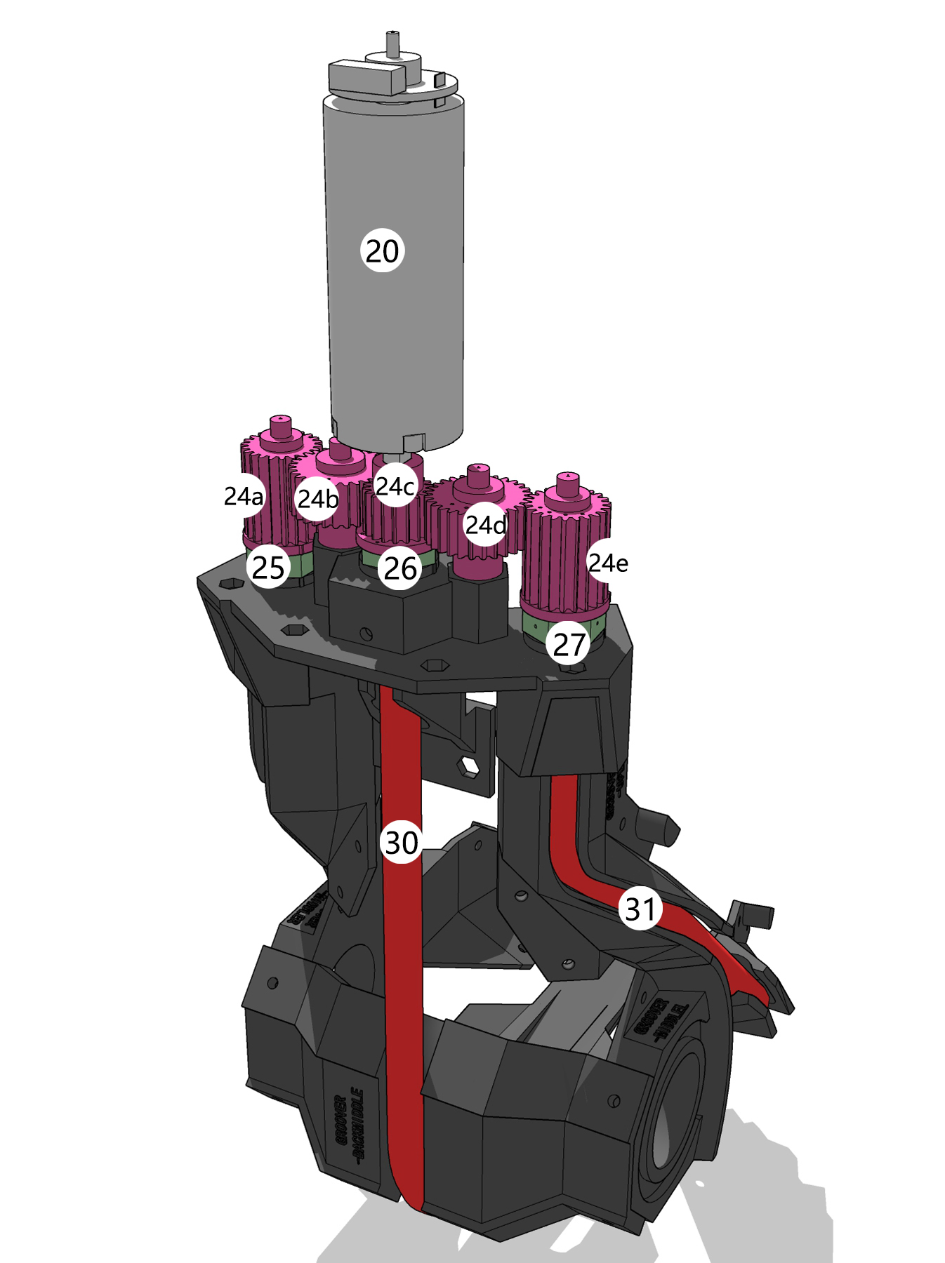
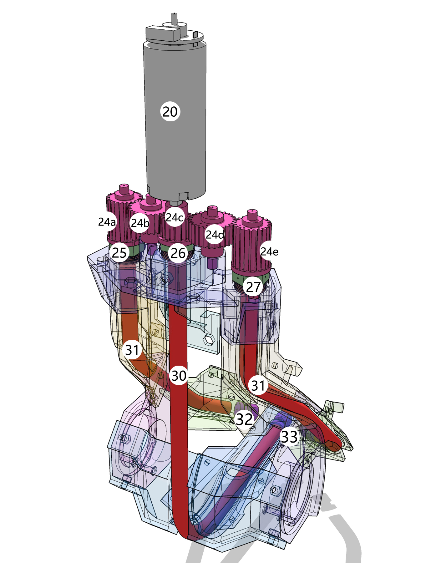
- Artificial muscle 30 pulls the forearm downward. Its power input is at 26 , and its anchor point is at 33 on the forearm.
- Artificial muscles 31 lift the forearm. Their power inputs are at 25 and 27 , and their anchor points are at 32 and 34 on the forearm.
- Gears 24c , 24a , and 24e rotate to contract and relax the artificial muscle bundles 30 and 31 respectively, or vice versa.
Assembly
1. Assembly Markings and Model Folder Description
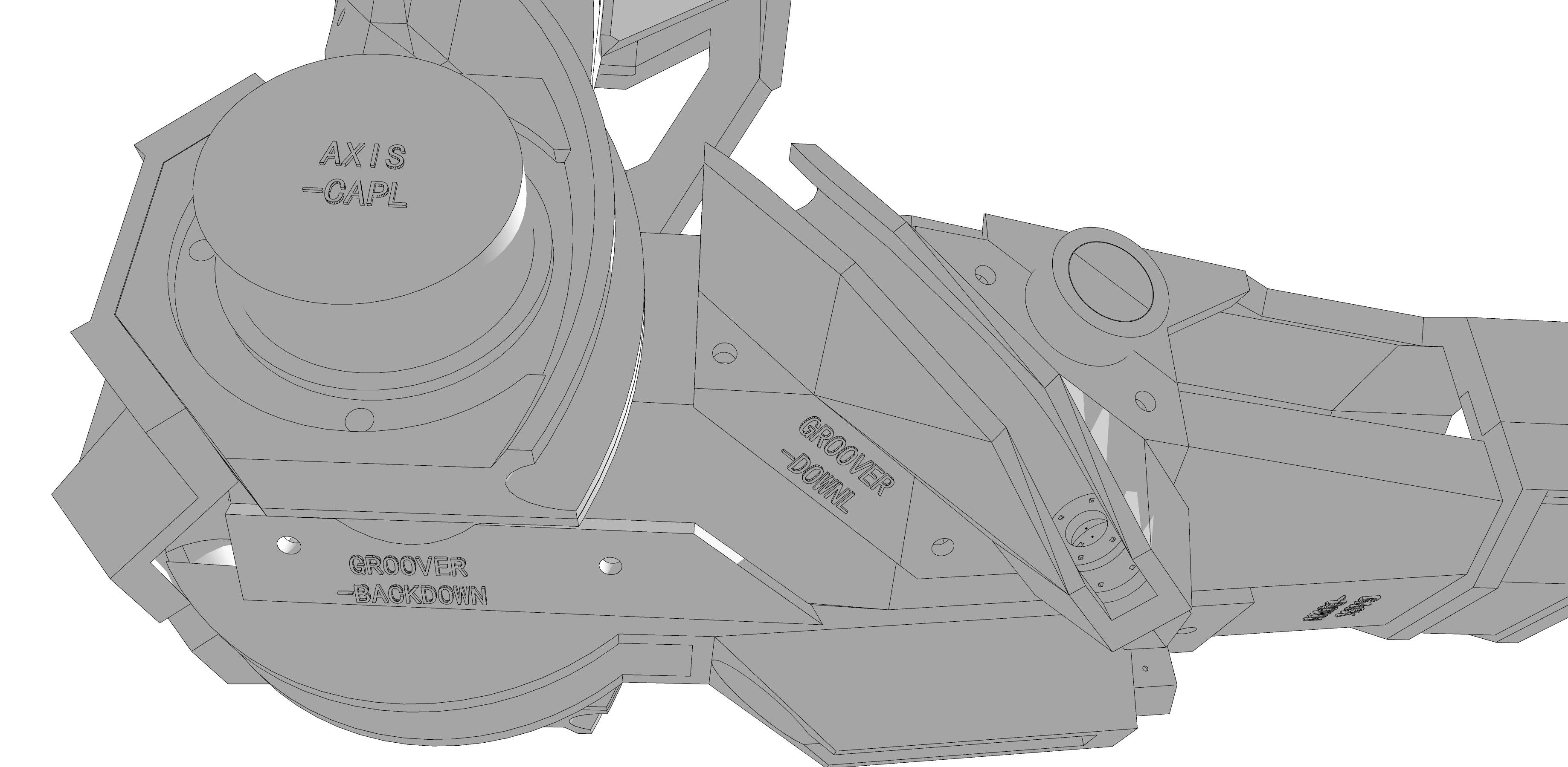
3D printed model surfaces are marked, and 3D print files are named according to these markings. For smaller parts where text markings are impractical, indentations are used instead. For example, the gear “GEAR-4.stl” has four indentations.
Model folder structure:
├── ANCHOR/
│   ├── ANCHOR-END0.stl
│   ├── ANCHOR-END2.stl
│   ├── ANCHOR-END4.stl
│   ├── ANCHOR-HEAD0.stl
│   ├── ANCHOR-HEAD2.stl
│   └── ANCHOR-HEAD4.stl
├── AXIS/
│   ├── AXIS-CAPL.stl
│   ├── AXIS-CAPR.stl
│   ├── AXIS-L.stl
│   └── AXIS-R.stl
├── BACK/
│   ├── BACK-DOWN.stl
│   └── BACK-UP.stl
├── BUCKLEx4/
│   └── BUCKLEx4.stl
├── COVER/
│   ├── COVER-DOWN.stl
│   └── COVER-UP.stl
├── GEAR/
│   ├── GEAR-0.stl
│   ├── GEAR-1.stl
│   ├── GEAR-2.stl
│   ├── GEAR-3.stl
│   └── GEAR-4.stl
├── GROOVER/
│   ├── GROOVER-BACKDOWN.stl
│   ├── GROOVER-BACKMIDDLE.stl
│   ├── GROOVER-BACKUP.stl
│   ├── GROOVER-DOWNL.stl
│   ├── GROOVER-DOWNR.stl
│   ├── GROOVER-MIDDLEL.stl
│   ├── GROOVER-MIDDLER.stl
│   ├── GROOVER-UPL.stl
│   └── GROOVER-UPR.stl
├── POWER/
│   ├── POWER-CAP1.stl
│   ├── POWER-CAP2.stl
│   └── POWER-CAP3.stl
└── SIDE/
    ├── SIDE-UPL.stl
    └── SIDE-UPR.stl
- Correspondence between labeled numbers and marked names:
| Number | Marked Name | Number | Marked Name | Number | Marked Name |
|---|---|---|---|---|---|
| 1 | SIDE-UPR.stl | 14 | GROOVER-MIDDLEL.stl | 24d | GEAR-3.stl |
| 2 | SIDE-UPL.stl | 15 | GROOVER-DOWNR.stl | 24e | GEAR-4.stl |
| 3 | BACK-DOWN.stl | 16 | GROOVER-DOWNL.stl | 25 | ANCHOR-HEAD0.stl |
| 4 | COVER-UP.stl | 17 | GROOVER-BACKUP.stl | 26 | ANCHOR-HEAD2.stl |
| 5 | COVER-DOWN.stl | 18 | GROOVER-BACKMIDDLE.stl | 27 | ANCHOR-HEAD4.stl |
| 6 | BACK-UP.stl | 19 | GROOVER-BACKDOWN.stl | 28 | Not provided |
| 7 | AXIS-R.stl | 20 | Not provided | 29 | BUCKLEx4.stl |
| 8 | AXIS-L.stl | 21 | POWER-CAP1.stl | 30 | Not provided, in R&D |
| 9 | AXIS-CAPR.stl | 22 | POWER-CAP2.stl | 31 | Not provided, in R&D |
| 10 | AXIS-CAPL.stl | 23 | POWER-CAP3.stl | 32 | ANCHOR-END0.stl |
| 11 | GROOVER-UPR.stl | 24a | GEAR-0.stl | 33 | ANCHOR-END2.stl |
| 12 | GROOVER-UPL.stl | 24b | GEAR-1.stl | 34 | ANCHOR-END4.stl |
| 13 | GROOVER-MIDDLER.stl | 24c | GEAR-2.stl |
2. Material Preparation
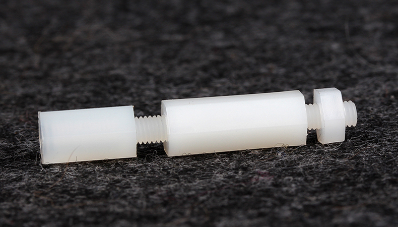

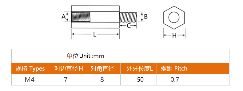
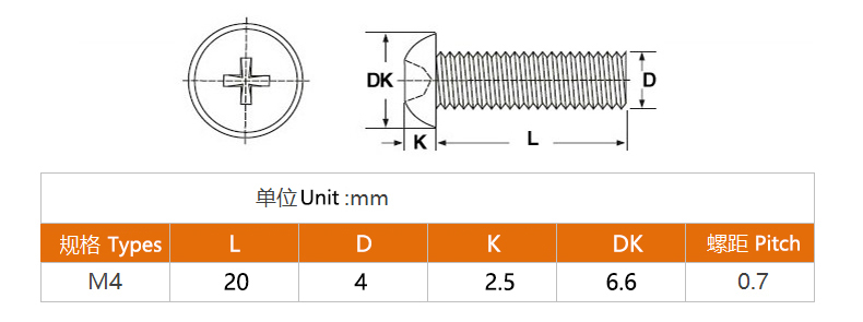
- Before assembly, prepare nylon screws, nuts, and hexagonal nylon spacers. Nylon is used instead of metal to allow customization by cutting if needed. The exoskeleton parts have hexagonal grooves where nuts can be embedded using 502 glue.
- At least 57 nylon M4 nuts and screws (screw length 20mm, nut width across flats 7mm); at least 6 hexagonal nylon spacers, 50mm long, M4 thread.
- Two Velcro straps, 20mm wide, at least 400mm long.
- 502 glue for fixing nuts.
3. Assembly Sequence
How to Model
- Collect key dimensions of your upper limb to form cross-sections, such as for the forearm:
- 1 : Wrist
- 2 : Point where wrist width changes
- 3 : Widest part of the forearm
- 4 : End of the elbow
- 5
: Thickest part of the forearm
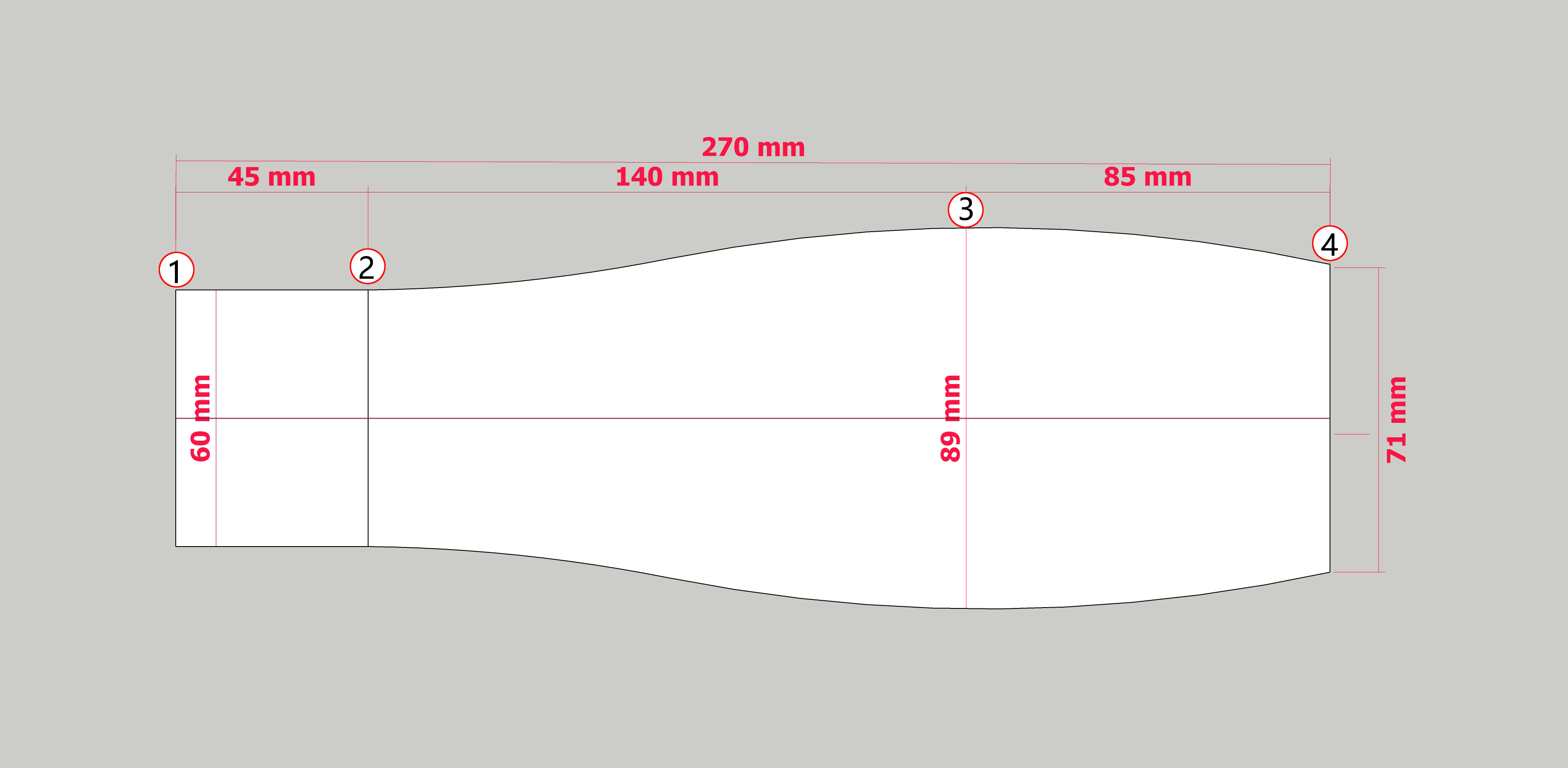
Forearm Top View 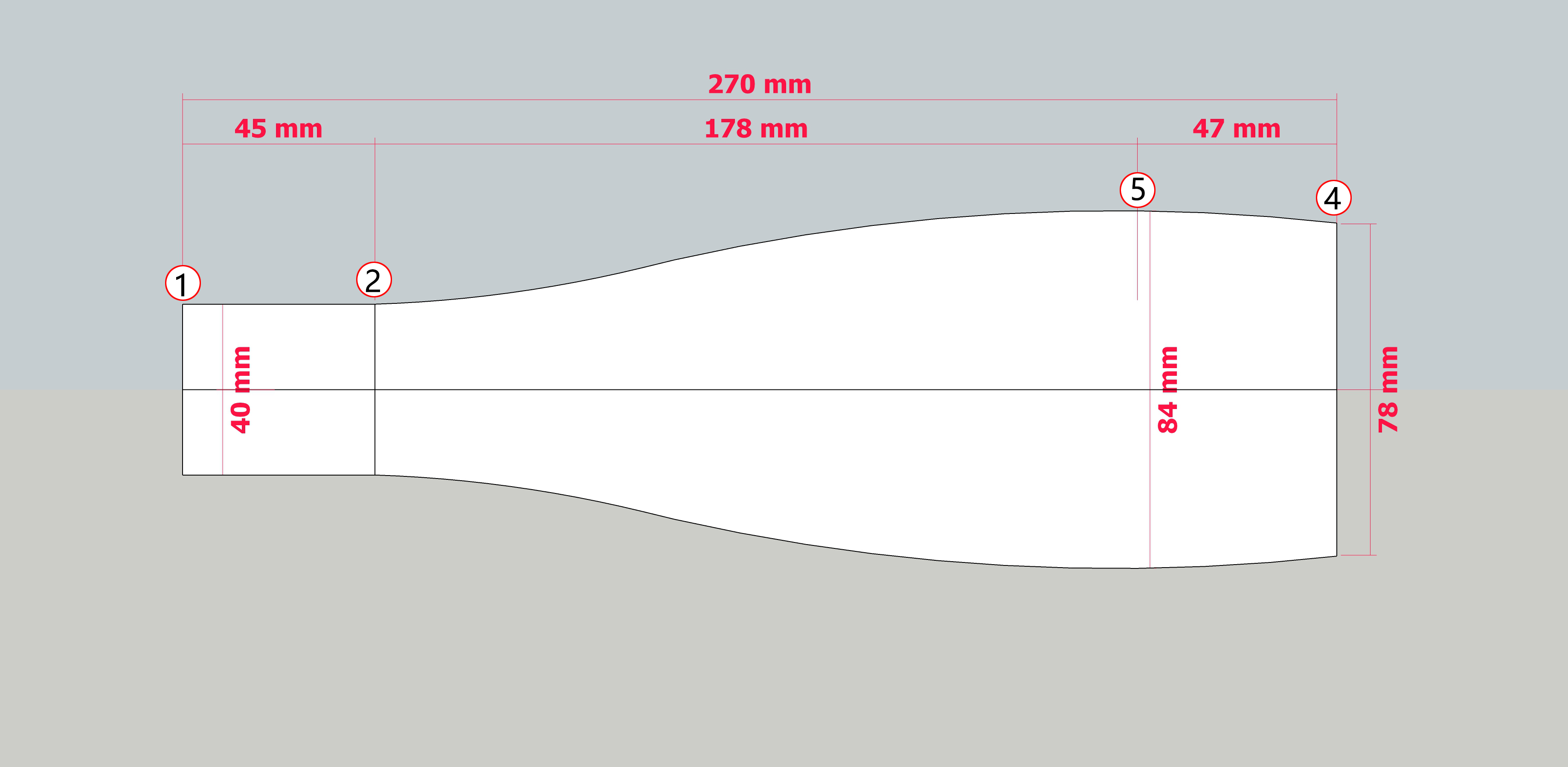
Forearm Side View 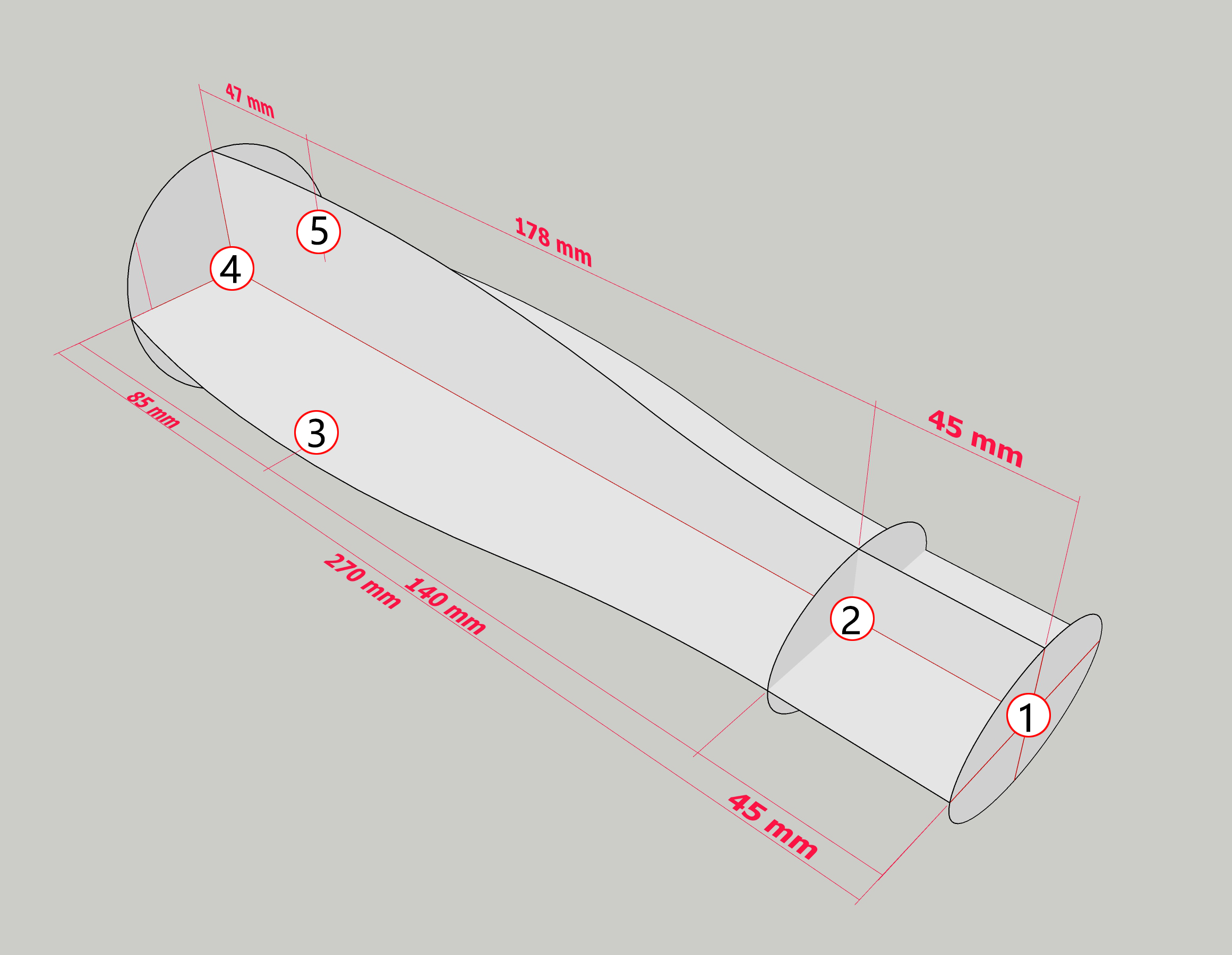
Forearm Cross section
- The forearm is an asymmetrical prism, not axially symmetric, with slanted upper and lower surfaces. Optimize the cross-sections from step 1, replacing curves with planes where possible. Process the upper arm similarly.
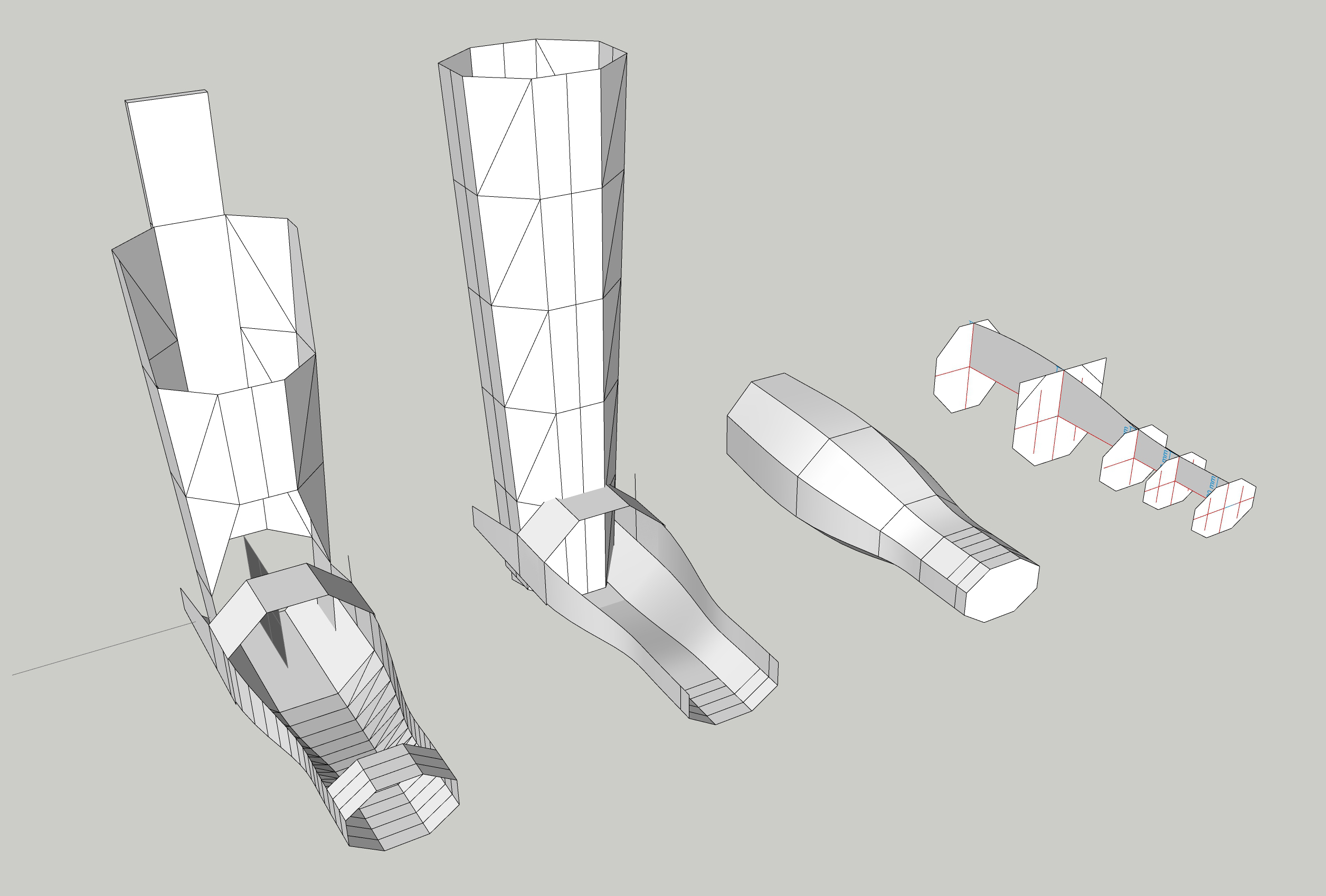
Optimization Process
3.Check for collisions between the upper and forearm sections, and refine as needed.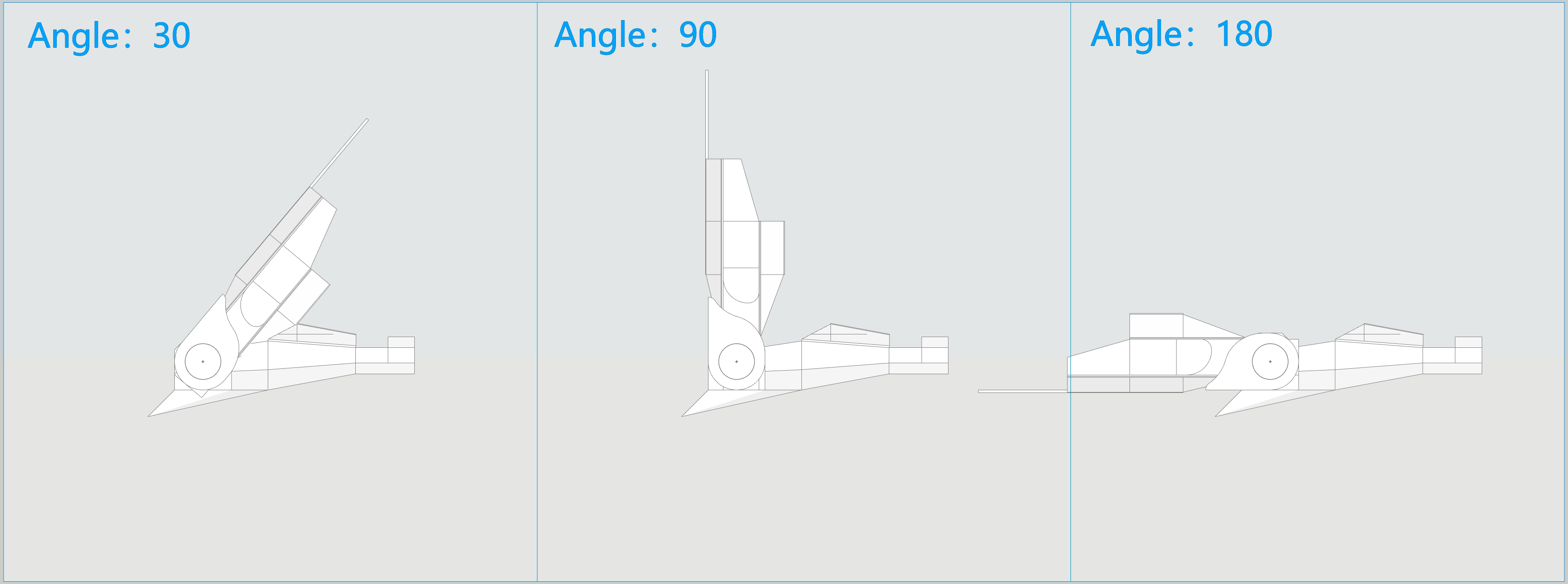
- The rest is up to aesthetics.